Wayside Fiber, Part 1: Where It Is
The physical plant: why signaling went to glass, what lives inside a 48-strand cable, how a midspan access works without touching the express path, and how a loss budget quietly fails at the far end of a fifty-mile corridor.
Part 1 of Wayside Fiber: the physical plant. The glass, the duct, the splices, and the light.
The corridor
The corridor runs 49.5 miles. At MP 0.0, Waverly: dispatch, the control center, the headend comms room. At MP 9.2, CP Arden, a control point with a grade crossing. At MP 18.7, Int 187, intermediate signals. At MP 27.4, CP Bowman. At MP 38.1, Det 381, a defect detector that does not exist yet when the cable goes in. At MP 49.5, CP Chester, the junction with a connecting railroad.
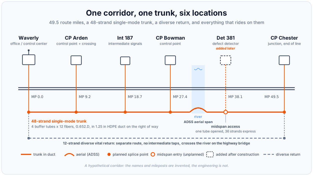 The corridor. The 48-strand trunk ties all six locations together; the dashed second route is a decision this part will have to pay for.
Tying them together: one 48-strand single-mode cable. Forty-eight sounds like absurd surplus for six locations; the discipline of this part is discovering it is not. (We run 48 here so the arithmetic stays visible on a page. Engineering from scratch, pull 96 or more: the glass is the cheapest thing in a trench you only want to open once.) Treat the strand count as a bank balance: it opens at 48 dark fibers, and every decision from here on makes a withdrawal. Watch the meter.
Why fiber, for signals specifically
Every industry has its reasons for fiber. Signaling has three that are its own.
Fiber is dielectric. A signal house is a defended electrical island, and every copper pair entering it is a liability to bond, protect, and arrest. When lightning strikes near a remote location, the earth there rises thousands of volts above remote ground; a copper pair carries that difference, ground potential rise, straight to the racks. Glass carries none of it: no bonding studs, no arresters to inspect, no path by which a strike at CP Arden visits Waverly. For plant that runs beside the track through miles of open country, this alone justified the transition.
Fiber does not care about the railroad's own noise. Track is an electrically hostile neighborhood: traction return current in electrified territory, inverter and chopper harmonics from modern locomotives, code pulses in the rail. Copper circuits in that environment are an unending EMC negotiation. Fiber simply opts out.
Fiber does distance. Our corridor is a fifty-mile campus. Single-mode glass covers it without a single repeater, amplifier, or powered device between houses. Every powered element you do not install is one that cannot fail, cannot be stolen, and does not need a meter socket in the middle of nowhere.
What did it replace? The pole line: open copper carrying line circuits and the code line, the low-speed serial channel by which the office polled the field. Code line worked, and versions survive, but it moved a few dozen indications per location, slowly; it could never carry an event recorder download, a video feed, or the constant vital chatter between modern processors. The pole line was also the most maintenance-hungry asset most railroads owned. The trunk replaced all of it at once, which is why it now carries responsibilities no single asset ever has.
What is actually in the cable
The cable is a loose tube design: 4 buffer tubes, each containing 12 fibers, 48 strands total, on G.652.D single-mode glass. The fibers float loosely inside dry water-blocked plastic tubes (gel-filled, in the older generation; dry core is the modern default, and the splicer who no longer cleans gel at 2 a.m. knows why) wrapped around a central strength member. The looseness is the point: the cable can be tensioned, bent, and thermally cycled while the glass inside stays unstressed.
Identification is by the TIA-598 color code, applied twice: once to the tubes, once to the fibers inside each tube.
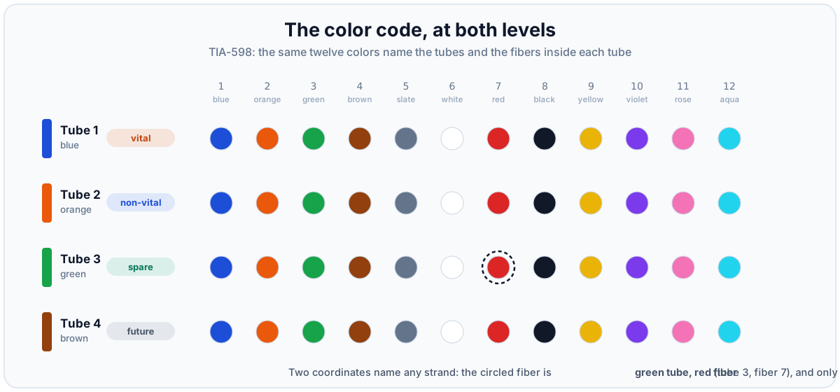 The same twelve colors name the tubes and the fibers. Two coordinates identify any one of the 48 strands.
The sequence is worth memorizing: blue, orange, green, brown, slate, white, red, black, yellow, violet, rose, aqua. Our cable has four tubes, so only the first four tube colors are used, but the fibers inside each run the full twelve. "Green tube, red fiber" names exactly one strand of glass out of 48, anywhere on the corridor, in any vault, at either end. That naming convention is the atom of every record we will keep in Part 3.
Construction outside the sheath is a set of environment choices:
- In duct is the default here: 1.25-inch HDPE conduit trenched or plowed into the right of way, cable pulled or jetted in later. The duct costs more up front and pays for itself the first time the cable must be replaced, upgraded, or repaired without re-excavating fifty miles.
- ADSS aerial (all-dielectric self-supporting) handles the river crossing near Bowman: a cable that needs no messenger wire and, being fully dielectric, can share structures without bonding concerns.
- Direct bury with armored cable was rejected: cheaper on day one, paid back with interest at every repair, and armor puts a metallic element (grounded at every entry) into an otherwise dielectric plant. The corridor stays dielectric end to end.
Allocating the tubes
Forty-eight strands is not one pool; it is four tubes, and tubes, not fibers, are the practical unit of separation, because a tube is what you break out at a splice point. So the allocation happens at tube level first:
| Tube | Color | Role |
|---|---|---|
| 1 | Blue | Vital: safety-critical communications only |
| 2 | Orange | Non-vital essential: SCADA, detectors, voice, CCTV |
| 3 | Green | Spare and test |
| 4 | Brown | Future: unopened, spliced straight through everywhere |
Spend the first tube. Vital traffic gets tube 1 in its entirety, even though it needs only a pair, because the boundary you enforce in glass is one no misconfiguration can cross. Tube 2 takes everything essential but non-vital. Tube 3 holds spares and a permanently dark test pair. Tube 4 is never even opened: at every splice location except the two ends, its buffer tube passes through the enclosure uncut. Unopened glass is the cheapest insurance the corridor will ever buy.
The meter, after initial allocation: 10 fibers lit or committed, 38 dark. (Vital forward pair, plus eight working fibers in tube 2.)
Chain or ring?
The obvious topology is a chain: one fiber pair hopping location to location down the line. It works, with a failure mode nobody accepts twice: any single cut splits the corridor, and everything beyond it goes dark to the office.
The alternative is a ring: traffic flows both ways around a loop, so any single failure leaves every location reachable the long way around. The cheap way to close the loop is a second pair in the same cable, tube 1 fibers 3 and 4, express from Waverly to Chester. On the drawing it is a ring: a blown optic or a bad splice heals invisibly, and a failed switch isolates only its own location.
But the single-point-of-failure analysis has to run against the realistic threat, and that is not a blown optic. It is a shovel. Both directions of a same-sheath ring share one trench, so the corridor's most likely failure, a dig-in, takes both paths in one bite. That is redundancy against the rare failures and none against the common one; for vital traffic, not a compromise available to us.
So the corridor buys real diversity and pays what it costs: a 12-strand return cable on a physically separate route, opposite side of the right of way where geometry allows, along the highway where it does not, crossing the river on the highway bridge half a mile from the trunk's ADSS span. Waverly to Chester direct, no intermediate taps, one job: close the loop. With it in place, no single cut on either cable can split the corridor.
Diversity is bought in route-miles, not strands: a second trench, a second set of locates, a second cable to test and document forever. Two disciplines keep it worth the money. First, "separate route" is verified on the ground, not on the drawing: two cables that share a bridge, a culvert, or a hundred feet of duct bank share a failure there, and that hundred feet becomes the ring's true weak point. Second, the return cable stays lean. It closes the ring and holds restoration spares, and it must not quietly grow into a second trunk, because every service that migrates onto it is a service that dies with it.
The meter after the ring decision, and the trunk allocation as built:
| Tube | Fibers | Assignment | Status |
|---|---|---|---|
| 1 blue | 1-2 | Vital ring, forward path (hop by hop) | lit |
| 1 blue | 3-12 | Reserved: vital only | dark |
| 2 orange | 1-2 | Code line to CP Chester (low-speed serial) | lit |
| 2 orange | 3-4 | Voice and maintenance access | lit |
| 2 orange | 5-8 | CCTV at two control points | lit |
| 2 orange | 9-12 | Spare, non-vital | dark |
| 3 green | 1-2 | Test and restoration pair | dark, reserved |
| 3 green | 3-12 | Unassigned spare | dark |
| 4 brown | 1-12 | Future | dark, unopened |
The new cable is kept deliberately boring: fibers 1 and 2 close the ring, 3 and 4 are its test pair, and the remaining eight are restoration spares.
One row needs its footnote: the corridor's own interlockings speak Ethernet and need no code line. The pair exists because the connecting railroad at Chester still polls its interface equipment the old way, and two strands humor it until the neighbor modernizes.
Running total: trunk, 10 lit, 12 reserved, 26 spare; return cable, 2 lit, 10 dark. Nearly half the trunk is spoken for before the first train sees a signal off this system. This is why 48 was never absurd.
Midspan access: the centerpiece
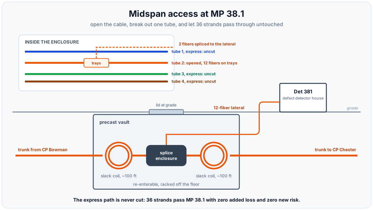
Two years after cutover, the railroad adds a defect detector at MP 38.1. No splice point exists there; the nearest are Bowman, 10.7 miles west, and Chester, 11.4 miles east, and the cable runs right past the site. The wrong answer is to cut all 48 fibers and splice all 48 back, taxing every strand on the corridor for one detector. The right answer is a midspan access, the most elegant maneuver in outside plant work:
Midspan access at MP 38.1. One tube opened; 36 strands pass through without being touched.
A crew exposes the cable, sets a precast vault, and pulls a hundred feet of slack from each direction, coiled inside. The slack is what makes the operation possible: it brings the enclosure above grade to a work table, and it is the reserve a future repair draws on. In the enclosure the sheath is opened over a few feet, and then the discipline: only tube 2 is cut. Its twelve fibers land on trays, two fused to a twelve-fiber lateral into the new detector house. Tubes 1, 3, and 4 are coiled and stored intact, express through the case. The vital ring passes MP 38.1 with zero added splices, zero added loss, zero new failure modes.
What the crew leaves on paper matters as much as what it leaves in the vault. The standard artifact is the splice sheet: one per enclosure, one row per strand or range. Formats vary by railroad; the columns do not. For SC-38.1:
| Cable / strand | Color code | Disposition | Tray-slot | Lands on | Circuit | Loss (dB) |
|---|---|---|---|---|---|---|
| Trunk T1, F1-F12 | BL tube | express, uncut | stored | trunk east, same strands | VRING + vital reserve | none added |
| Trunk T2, F1-F8 | OR-BL thru OR-BK | fusion, straight through | T2-01 thru T2-08 | trunk east, same strands | code line (F1-F2) + spares | 0.08 max |
| Trunk-W T2, F9 | OR-YL | fusion | T2-09 | lateral F1 (BL) | DET-381-A | 0.07 |
| Trunk-W T2, F10 | OR-VI | fusion | T2-10 | lateral F2 (OR) | DET-381-B | 0.05 |
| Trunk-E T2, F9-F10 | OR-YL, OR-VI | stored on tray, dark | T2-11, T2-12 | nothing (east legs of the cut pair) | spare | n/a |
| Trunk T2, F11-F12 | OR-RS, OR-AQ | fusion, straight through | T2-13, T2-14 | trunk east, same strands | spare, continuous | 0.08 max |
| Trunk T3, F1-F12 | GN tube | express, uncut | stored | trunk east, same strands | test + spare | none added |
| Trunk T4, F1-F12 | BN tube | express, uncut | stored | trunk east, same strands | future | none added |
| Lateral F3-F12 | GN thru AQ | on tray, dark | T2-15 thru T2-24 | future at Det 381 | spare | n/a |
Color codes read tube first, fiber second: OR-BL, orange tube, blue fiber, exactly one strand of glass. Fusion losses are the bidirectional OTDR average at 1550 nm, measured after the case was closed and racked, because sealing re-stresses splices. And the "nothing" row is information, not embarrassment: the east legs dead-end here by design, and the sheet says so before someone tones them for two hours in 2033.
The lateral has two ends, and the record follows it into the house. FDP-38.1 is the smallest panel on the corridor, and it gets the same sheet as everything else:
| Cable / strand | Color code | Disposition | Tray-slot | Lands on | Circuit | Loss (dB) |
|---|---|---|---|---|---|---|
| Lateral F1 | BL | fusion to pigtail | T1-01 | port 01 | DET-381-A | 0.05 |
| Lateral F2 | OR | fusion to pigtail | T1-02 | port 02 | DET-381-B | 0.04 |
| Lateral F3-F12 | GN thru AQ | stored on tray, dark | T1-03 thru T1-12 | nothing (unassigned) | future | n/a |
Two things to notice. A single-tube lateral carries a one-coordinate color code: F1 is just BL; the sheet does not invent a tube that does not exist. And DET-381-A is now traceable end to end with no gaps: Waverly's port map onto trunk T2-F9, straight-through rows at each entrance sheet, SC-38.1 onto lateral F1, this sheet onto port 01 and its tagged jumper. Ports 03-12 sit dark behind ten dark strands, waiting for whatever Det 381 grows next.
Thirty-six strands untouched, ten spliced straight through on trays, two put to work. The trunk's meter moves to 12 lit (two orange spares became the detector's feed), and the corridor gains its seventh splice location, one that appears on no original drawing. Hold that thought for Part 3.
Into the house
At each location the trunk's story ends the same way. A lateral leaves a vault, enters the house through conduit, and lands in a fiber distribution panel, the FDP. This is the boundary between two worlds: outside plant cable, which is water-blocked, armored against the environment, and never connectorized in the field, and inside plant, which is connectors, jumpers, and equipment.
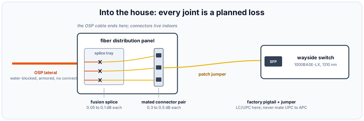 The FDP is where cable becomes connectors. Each element in the chain has a known, budgeted loss.
Inside the FDP, each working fiber is fusion spliced to a factory-made pigtail: a short fiber with a connector already polished onto one end. The pigtail's connector snaps into the back of an adapter panel, presenting a clean, labeled port on the front. From there a patch jumper runs to the SFP optic in the wayside switch. Nobody hand-polishes connectors in a signal house; the factory pigtail plus fusion splice is faster, better, and measurable.
The trays inside the FDP are an enclosure like any other, and they get the same artifact: an entrance splice sheet, one row per strand, covering both trunk legs where they land in the house. Here is CP Bowman's. Note that the trunk is not fully cut at a house any more than it was at the midspan: only the tubes with business here are opened, and tubes 3 and 4 never enter the trays at all.
| Cable / strand | Color code | Disposition | Tray-slot | Lands on | Circuit | Loss (dB) |
|---|---|---|---|---|---|---|
| Trunk-W T1, F1 | BL-BL | fusion to pigtail | T1-01 | port 01 | VRING west | 0.04 |
| Trunk-W T1, F2 | BL-OR | fusion to pigtail | T1-02 | port 02 | VRING west | 0.06 |
| Trunk-E T1, F1 | BL-BL | fusion to pigtail | T1-03 | port 03 | VRING east | 0.05 |
| Trunk-E T1, F2 | BL-OR | fusion to pigtail | T1-04 | port 04 | VRING east | 0.03 |
| Trunk T1, F3-F12 | BL-GN thru BL-AQ | fusion, straight through | T1-05 thru T1-14 | trunk east, same strands | vital reserve, continuous | 0.08 max |
| Trunk T2, F1-F2 | OR-BL, OR-OR | fusion, straight through | T2-01, T2-02 | trunk east, same strands | code line, through | 0.06 max |
| Trunk-W T2, F3 | OR-GN | fusion to pigtail | T2-03 | port 05 | VOICE-BOW | 0.05 |
| Trunk-W T2, F4 | OR-BN | fusion to pigtail | T2-04 | port 06 | VOICE-BOW | 0.04 |
| Trunk-W T2, F5 | OR-SL | fusion to pigtail | T2-05 | port 07 | CCTV-BOW | 0.06 |
| Trunk-W T2, F6 | OR-WH | fusion to pigtail | T2-06 | port 08 | CCTV-BOW | 0.05 |
| Trunk-E T2, F3-F6 | OR-GN thru OR-WH | stored on tray, dark | T2-07 thru T2-10 | nothing (circuits serve this house from the west) | reserved | n/a |
| Trunk T2, F7-F8 | OR-RD, OR-BK | fusion, straight through | T2-11, T2-12 | trunk east, same strands | spare, continuous | 0.08 max |
| Trunk T2, F9-F10 | OR-YL, OR-VI | fusion, straight through | T2-13, T2-14 | trunk east, same strands | DET-381 feed, through | 0.06 max |
| Trunk T2, F11-F12 | OR-RS, OR-AQ | fusion, straight through | T2-15, T2-16 | trunk east, same strands | spare, continuous | 0.08 max |
| Trunk T3 + T4 | GN, BN tubes | express, uncut | stored in slack loop | trunk east, same strands | test, spare, future | none added |
The same disciplines, indoors. Pigtail rows are the entrance splices proper, each shot against the 0.10 dB acceptance limit before the tray closes. Straight-through rows keep reserves continuous end to end, so a dark tube 1 fiber can be tested Waverly to Chester without a truck roll. (A choice, not a law: some designs store unused fibers uncut and save the reserve four splice points. This corridor paid the 0.3 dB for testability, and wrote it down.) And again the sheet records the nothing: the east voice and CCTV legs land on no pigtail, by design, and the row saying so is the cheapest troubleshooting the corridor will ever buy.
The FDP gets its own standard artifact, the port map: one row per connectorized port, tying panel position to strand to circuit to equipment. Here is CP Bowman's, panel FDP-27.4:
| Port | Strand | Color code | Circuit | Jumper to | Status |
|---|---|---|---|---|---|
| 01 | Trunk-W T1, F1 | BL-BL | VRING west, to Int 187 | SW-BOW, SFP 25 | in service |
| 02 | Trunk-W T1, F2 | BL-OR | VRING west | SW-BOW, SFP 25 | in service |
| 03 | Trunk-E T1, F1 | BL-BL | VRING east, to CP Chester | SW-BOW, SFP 26 | in service |
| 04 | Trunk-E T1, F2 | BL-OR | VRING east | SW-BOW, SFP 26 | in service |
| 05 | Trunk-W T2, F3 | OR-GN | VOICE-BOW, to Waverly | channel bank | in service |
| 06 | Trunk-W T2, F4 | OR-BN | VOICE-BOW | channel bank | in service |
| 07 | Trunk-W T2, F5 | OR-SL | CCTV-BOW, to Waverly | video encoder | in service |
| 08 | Trunk-W T2, F6 | OR-WH | CCTV-BOW | video encoder | in service |
| 09-24 | none | reserved | dark |
Read what the table does not list, because that is half its value: tube 1 fibers 3-12 and tube 2 fibers 1-2 and 7-12 have no port appearance at this house, passing through on splice trays without ever touching a connector, and tubes 3 and 4 pass the house entirely uncut. A strand only earns a connector where a circuit terminates. (Voice and CCTV on dedicated glass are the older generation; when their equipment is replaced, the traffic moves onto the switch, the strands go back to spare, and the port map records both.) All of these artifacts key on the same strand names, which is what makes them one record instead of three.
That leaves the last two feet of every circuit: the patch jumpers between the panel and the equipment, and they get the humblest record in the set, the jumper schedule:
| Jumper | From | To | Cord | Circuit |
|---|---|---|---|---|
| J-BOW-01 | FDP-27.4, ports 01-02 | SW-BOW, SFP 25 | duplex LC/UPC, 10 ft | VRING west |
| J-BOW-02 | FDP-27.4, ports 03-04 | SW-BOW, SFP 26 | duplex LC/UPC, 10 ft | VRING east |
| J-BOW-03 | FDP-27.4, ports 05-06 | channel bank, optical A | duplex LC/UPC, 6 ft | VOICE-BOW |
| J-BOW-04 | FDP-27.4, ports 07-08 | video encoder, optical 1 | duplex LC/UPC, 15 ft | CCTV-BOW |
Two strands make one circuit, so ports come in pairs and a duplex cord carries transmit and receive into one SFP, crossover built into the cord. Each jumper wears its ID and circuit on flag tags at both ends, and cords are ordered to measured length: excess coils are how a house grows the spaghetti nobody dares touch.
Do not let the table's humility fool you. Everything underground changes with a crew and a permit; a jumper changes with one hand, in ten seconds, with no paperwork. That asymmetry makes the jumper schedule the most frequently wrong document in the plant: documentation discipline dies at the patch panel, not on the right of way. The rule is the vault's rule: the record is part of the work. A moved jumper updates the schedule in the same visit, or the schedule is fiction by lunchtime. The payoff: a tech at 2 a.m. traces any link by reading, without tugging a live circuit to see what wiggles.
One detail bites people for years if it is gotten wrong: connector polish. UPC connectors (blue housings, flat-domed polish) are the norm for data links like ours. APC connectors (green housings, 8-degree angled polish) exist for applications where reflectance matters, such as RF-over-fiber video. The two do not mate. Forcing a UPC jumper into an APC port yields an air gap, a huge loss, and shattered end faces if you are unlucky. On this corridor everything is LC/UPC, the As-built says so, and any green connector found in a house is treated as a defect.
The strand ledger
Splice sheets and port maps are each true about one place. The strand ledger is true about the corridor: one row per strand or range, per cable, answering "what is this fiber doing, end to end, right now." It is the sheet you open first, the one every other sheet must agree with, the one Part 3's change process exists to protect. As of the detector cutover:
| Cable | Strands | Assignment | Runs | Status |
|---|---|---|---|---|
| Trunk | T1, F1-F2 | VRING forward | section by section; terminates at the five signal houses, passes SC-38.1 uncut | lit |
| Trunk | T1, F3-F12 | vital reserve | continuous, Waverly to Chester | dark, reserved |
| Trunk | T2, F1-F2 | code line to CP Chester | Waverly to Chester, no intermediate drops | lit |
| Trunk | T2, F3-F4 | VOICE-BOW | Waverly to Bowman; dark east of MP 27.4 | lit to MP 27.4 |
| Trunk | T2, F5-F6 | CCTV-BOW | Waverly to Bowman; dark east of MP 27.4 | lit to MP 27.4 |
| Trunk | T2, F7-F8 | CCTV-ARD | Waverly to Arden; dark east of MP 9.2 | lit to MP 9.2 |
| Trunk | T2, F9-F10 | DET-381-A/B | Waverly to SC-38.1, onto the lateral; east legs dark | lit to MP 38.1 |
| Trunk | T2, F11-F12 | spare, non-vital | continuous | dark |
| Trunk | T3, F1-F2 | test and restoration pair | continuous, uncut at every house | dark, reserved |
| Trunk | T3, F3-F12 | spare | continuous | dark |
| Trunk | T4, F1-F12 | future | continuous, tube never opened | dark |
| Return | F1-F2 | VRING closure | Waverly to Chester direct, highway route | lit |
| Return | F3-F4 | test pair | Waverly to Chester direct | dark, reserved |
| Return | F5-F12 | restoration spares | Waverly to Chester direct | dark |
| Lateral-381 | F1-F2 | DET-381-A/B | SC-38.1 to FDP-38.1 | lit |
| Lateral-381 | F3-F12 | future at Det 381 | SC-38.1 to FDP-38.1 | dark |
Seventy-two strands: 16 lit, 14 reserved, 42 spare or future. The "Runs" column does the quiet work, holding the truth no local sheet can: a strand can be lit in one section and dark in another, and only the ledger knows both at once. Corridor totals live here and nowhere else; splice sheets tell you what each room believes, and the ledger is where beliefs are forced to agree. When Part 2 builds an addressing record with exactly this shape, it is copying the oldest good idea in the fiber plant.
The loss budget
Light leaves an SFP with a known power and a receiver needs a known minimum. The difference is the budget, and everything between the two optics spends it. The ring's forward path is lit hop by hop between the five signal houses (Det 381 is not one of them: the vital ring passed MP 38.1 uncut, remember, and the detector hangs off its own tube 2 pair). That makes four hops: three short ones at 8.7 to 9.5 miles, and one long one, Bowman to Chester, at 22.1 miles. Run the same discipline the table below uses, spec attenuation, 0.10 dB per splice, four mated connector pairs, three dB of margin, and the short hops each price out at 10 to 11 dB at 1310 nm, the long one at about 13 dB run at 1550. Notice what that arithmetic quietly disqualifies: ordinary 1000BASE-LX, nominally a 10 km part with roughly 9.5 dB to spend, comes up short even on the shortest hop once honest margin is counted, and an optic that works only on factory margin is a failure on layaway. So the forward path gets 1000BASE-EX, the 40 km class at around 18 dB, on the short hops, one spared part number for three spans, and a ZX at 1550 for Bowman to Chester. Topology still does the heavy lifting; the houses just have to be honest about the arithmetic between them.
The ring's closure span is a different animal, because it cannot hop: there are no houses on the highway route, and its whole purpose is to reach Chester without depending on anything in between. It is one lit span, and the highway routing makes it longer than the railroad: 52.3 route miles against the corridor's 49.5. One number before the tally: single-mode glass loses about 0.56 dB per mile at 1310 nm and 0.35 dB per mile at 1550. (Spec sheets quote 0.35 and 0.22 dB/km; same glass, different ruler.) Run the tally at 1550 nm:
| Item | Quantity | Unit loss | Subtotal |
|---|---|---|---|
| Fiber attenuation | 52.3 mi | 0.35 dB/mi | 18.3 dB |
| Fusion splices (reel joints + entries) | 21 | 0.10 dB | 2.1 dB |
| Mated connector pairs (adapter panel + SFP receptacle, each end) | 4 | 0.50 dB | 2.0 dB |
| Design margin (aging, repairs, future work) | 3.0 dB | ||
| Required budget | 25.4 dB |
Note what is honest in this table. Splices are budgeted at 0.10 dB even though a good fusion splice measures 0.03; you budget the acceptance limit, not the best case. And three dB of margin is not padding, it is the span's future: every repair splice this cable ever needs must fit inside it.
Now the failure. The obvious part for the job, a long-reach 1000BASE-ZX optic, offers roughly 21.5 dB of budget. Required: 25.4. (Count the connector pairs honestly: the signal chain drawn earlier has two mated pairs per end, the adapter panel and the SFP receptacle, not one.) The span does not close. Fit ZX optics anyway and the link may even come up on day one, riding on the vendor's factory margin, and then die quietly some winter after the first repair splice: the most expensive kind of failure, the one that passes commissioning. The far end of a long corridor is exactly where a surprising number of real projects discover their arithmetic.
The resolution here is optical, not architectural, because the architecture is the point: this span exists to have no dependencies. It gets EZX-class 1550 nm optics, rated around 33 dB, and closes with more than 7 dB to spare. The general lesson: let topology carry every budget it can, and spend real money on optics only for the spans whose independence is what you are buying.
Two procurement notes belong in the record beside that decision. EZX is a de facto class, not an IEEE name, and it usually means a third-party optic, which matters to a railroad that specs vendor-certified parts for vital equipment: qualify it deliberately and write down that you did. And spec the switches with 10G-capable uplink cages even though every optic installed today is gigabit; at current prices the delta is noise, and the day the legacy CCTV migrates onto the network, the upgrade should be an optic swap, not a switch replacement.
Proving it
An unproven fiber plant is a rumor. Two instruments turn it into a record, and they answer different questions.
The OTDR answers where. It fires pulses down the strand and times the backscatter, producing the trace: a long slope of attenuation punctuated by events, each with a distance. Shot from both ends (bidirectionally) and at both 1310 and 1550 nm, through a launch cable and into a receive cable, it characterizes every splice and connector individually. The cords are not ceremony: an OTDR cannot measure inside its own dead zone; without them the two end connectors, the most-handled joints on the strand, go uncharacterized. Bidirectional matters because a single-direction shot can report a splice as a gain, an artifact of mismatched backscatter between fiber spools; averaging the two directions yields the true loss. Both wavelengths matter because 1550 is far more sensitive to bending: an event that grows at 1550 but not 1310 is a stressed cable telling you about a future failure while it is still cheap to fix.
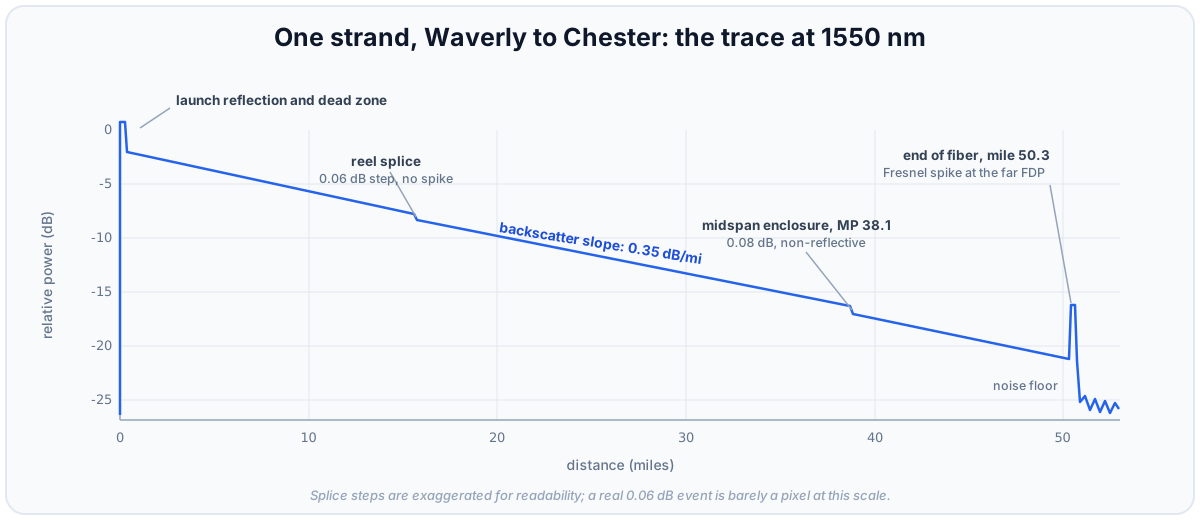 One strand, Waverly to Chester, at 1550 nm. Every event has a location, a loss, and now, a baseline value. Note the trace reads 50.3 cable miles for a 49.5-mile railroad: reel slack, entrance coils, and vault loops are distance too, and one to two percent of cable overage is normal.
The insertion loss test answers how much, in total: calibrated source at one end, power meter at the other, both wavelengths, both directions. It is the budget table's number, measured. Neither instrument substitutes for the other: OTDR losses are inferred from backscatter, not measured end to end, and a passing total says nothing about where trouble is accumulating. Acceptance means both, and the diverse return gets the same rigor as the trunk: an unproven protection path is not a path, it is a hope with a work order attached.
Treat the as-built drawings as a hypothesis and the OTDR as the experiment. If the trace shows an event at mile 38.7 and the drawings show no splice there, the drawings are wrong, and it is the drawings that get corrected. The set of accepted traces, filed with the records, is the plant's fingerprint. Part 3 turns that fingerprint into money.
Where this leaves the corridor
Every strand is proven, every budget closes, and in every house a switch port shows a steady green link LED to each neighbor. The physical plant is done.
And nothing can reach anything. No device has an address, no VLAN exists, no packet knows where to go. A lit link is not a network, only the possibility of one. What turns fifty miles of proven glass into a working railroad network, and the new ways it fails once that happens, is Part 2: How It Talks.